Identifying Solar Panel Problems Using Thermal Imaging (IR Thermography)
Solar panels can fail for many different reasons—poor connections, shading, cracks, or cell degradation. To maintain maximum energy yield, it’s important to detect these issues early. Among the available diagnostic methods, solar panel thermal imaging (infrared thermography) is one of the fastest and most reliable techniques.
Methods for Diagnosing Solar Panel Faults
There are several approaches to analyze the condition of a photovoltaic (PV) module:
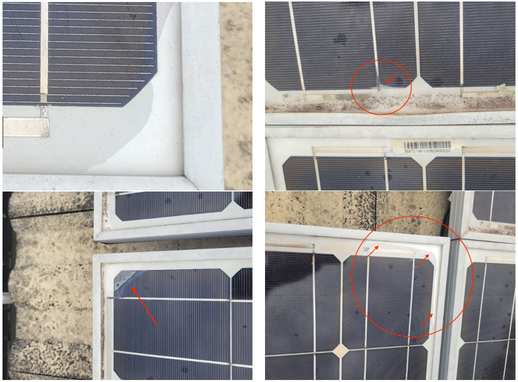
- Visual inspection – detects visible damage such as cracks or corrosion.
- I–V curve testing – measures current–voltage behavior to identify mismatch or short circuits.
- Electroluminescence (EL) imaging – reveals hidden cracks in dark conditions.
- UV fluorescence – highlights delamination or encapsulant defects.
- Thermal imaging (IR thermography) – shows temperature variations directly on the working module.
Each method has its advantages, but thermal imaging stands out because it can be performed quickly in the field under normal operating conditions.
What Is Thermal Imaging and How It Works
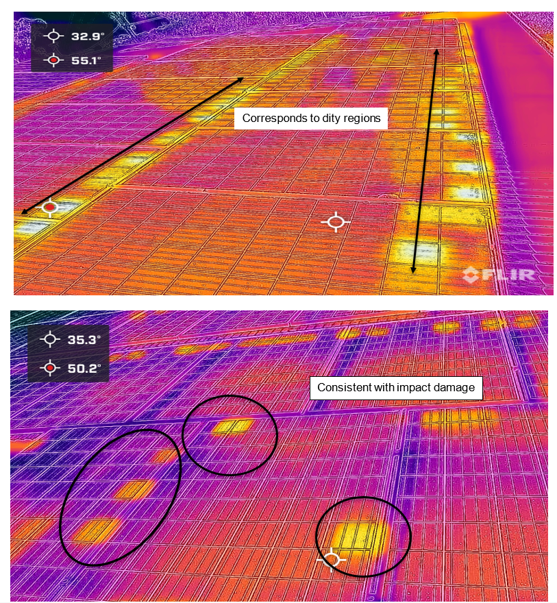
Thermal imaging, or infrared (IR) thermography, uses an IR camera to visualize temperature differences across a solar panel. Thermal imaging offers a non-destructive, real-time, on-site method. Under sunlight, electric current flows through every solar cell. Any area with higher resistance converts part of that current into heat, producing visible “hotspots” in the thermal image.
These temperature variations help identify electrical or mechanical faults that are invisible to the naked eye.
When to Perform Thermal Imaging
For accurate results, inspections should be carried out:
- On a clear, sunny day (irradiance > 600 W/m²).
- With the array operating under load so that current is flowing.
- From an angle perpendicular to the module surface to avoid reflection errors.
Why Faults Appear as Hotspots
Most PV faults increase resistance in a specific cell or connection. When current passes through this area, the high-resistance area dissipates energy as heat. The IR camera detects this heat difference and highlights the defective section. Large temperature differences (ΔT > 10 °C) usually indicate serious issues such as cracked cells, shorted bypass diodes, or potential-induced degradation (PID).
Common Thermal Imaging Patterns and Their Causes
|
Pattern |
Description |
Possible Cause of Failure |
Remark |
|---|---|---|---|
 |
One solar panel is warmer than the others |
|
|
 |
One substring (row) of the solar panel is warmer than the other substrings of the panel |
|
|
 |
Warmer cells throughout the solar panel |
|
|
 |
Single cells are warmer. The lower part of the solar panel close to the frame is hotter than the upper and middle parts. |
|
|
 |
One cell is warmer than all the other cells in the solar panel |
|
|
 |
Parts of a cell are warmer than the other parts |
|
|
 |
A single high-temperature point |
|
|
 |
Some parts of the substring are hotter than the others when equally shaded |
|
|
Thermal imaging makes it possible to identify early-stage defects before they reduce energy yield. By integrating IR inspections into routine maintenance, system owners can prevent hotspot damage, improve safety, and extend module lifespan.
Reference: Köntges, M., Kurtz, S., Packard, C., Jahn, U., Berger, K. A., Kato, K., et al. (2014). Review of Failures of Photovoltaic Modules (IEA-PVPS T13-01:2014). International Energy Agency Photovoltaic Power Systems Programme. https://iea-pvps.org